Loading situations
Trailer designs are often the result of experience and knowledge gained by manufacturing companies over the years, as well as the know-how of end users. Good solutions are generally also applicable for lightweight vehicles produced in high-strength steel. However, high-strength steel enables new solutions, but may also require design changes in order to leverage its higher strength.
A typical trailer chassis consists of two longitudinal main beams manufactured from either standardized hot-rolled profiles or welded I-beams, along with a variety of cross-member profiles. Cross-members can be made from open profiles, tubes or box-section profiles, depending on trailer type. Floor members and different support profiles can also be attached to the chassis. The king-pin region of the trailer usually consists of a king-pin plate and some reinforcement profiles.
The potential for upgrading a trailer chassis is generally limited not only by its static load-carrying capacity, but even more so by fatigue and stability issues. Therefore, while finding a solution with matching load-carrying capacity to the existing design serves as a good starting point, it is essential to address these other technical considerations in order to have a vehicle with matching or improved performance. It is important to note that poor design or production quality can rapidly reduce the vehicle life span.
The dimensioning load case for a trailer chassis manufactured from mild steel is generally its load-carrying capacity with regard to permanent deformations, as shown in the illustration below. In a light-weight trailer chassis, where thicknesses have been reduced and working stress levels increased, the load-carrying capacity and service life are limited by fatigue, elastic deflections and stability.
To achieve a successful upgrading it is important to take all loading situations into account,
1) Fatigue at frequent low stress loading cycles,
2) Elastic deformations when operating,
3) Load carrying capacity; no permanent deformations at maximum loading,
4) Stability when operating.
Typical upgrades
Strenx® 700MC is commonly used in lightweight solutions for trailer chassis. Upgrading a trailer chassis from a S355 (grade 50) grade to Strenx® 700MC (Strenx® 110 XF) typically generates a weight reduction of about 30% for the chassis structural parts. However, depending on the chassis design, the weight reduction potential may be even higher, up to 50%. As an example, we have calculated the potential weight reduction of an existing 13.75-meter-long trailer main beam produced from a S355 (grade 50) steel grade by introducing Strenx® 700MC. The load-carrying capacity of the existing design has been determined and a matching alternative in Strenx® 700MC is suggested in the illustration and table below.
The total weight of the original main members manufactured from conventional steel is 1,085 kg, and the total weight of the upgraded alternative in Strenx® 700MC is 704 kg. This gives a weight re-duction of 381 kg, or 35.2%. These results should be considered as an example. Depending on the type of vehicle, specific requirements and design details, the upgrading potential may be less or greater compared to our example. The calculations only consider static load-carrying capacity, but serve as a good starting point in developing a lightweight chassis design.
The main beams of a conventionally designed trailer chassis have limitations in using a strength higher than Strenx® 700MC for structural strength. Exploring other chassis concepts is necessary to truly benefit from higher strength. For certain special trailers, however, higher grades like Strenx® 960 may make an appropriate choice. For flanges or profiles that are susceptible to wear or dents, such as the rear bumper, a higher strength steel like Strenx® 1100 or a wear-resistant steel like Hardox® 450 can be specified. For other parts of the chassis, such as floor members, cold-rolled steels like Strenx® 700 CR and Strenx® 960 CR offer significant weight reduction opportunities. These parts can be produced by bending and, for larger series, roll-forming or stamping.
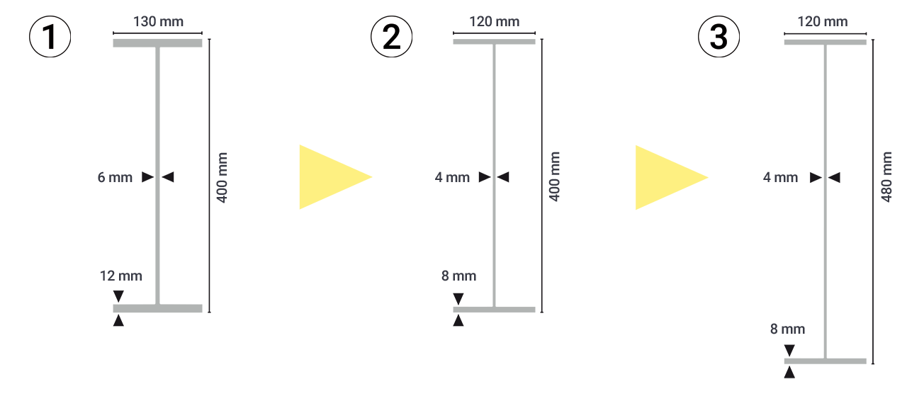
Overview of the cross-sectional properties and the weight reduction potential of a conventional main beam 1) and upgraded, lightweight alternatives 2) and 3) in Strenx® 700MC.
| 1) Original design | 2) Lightweight design | 3) Lightweight design | |
|---|---|---|---|
| Steel Grade | S355 | Strenx® 700 MC | Strenx® 700 MC |
| Weight, m [kg/m] | 42 | 27 | 30 |
| Bending Moment Capacity, M [kNm] | 286 | 306 | 369 |
| Moment of Inertia, I [%] | 100 | 66 | 100 |
| Section Modulus, W [%] | 100 | 64 | 81 |
| Weight Reduction, WR [%] | 100 | 36 | 30 |
Bending stiffness
Bending stiffness in the vertical direction is often cited as a critical aspect for lighter and stronger trailers in high-strength steel. In some markets, the elastic deflections of vehicles are regulated with regard to ground clearance, but in most cases, the limitations on deflections are a matter of functionality. That is, the deflections of the trailer chassis should not introduce problems in opening and closing doors. For certain special trailers, such as low-bed trailers, the requirements on the elastic deflections may limit the choice of material.
Since all steel grades have the same Young’s modulus, the bending stiffness is determined by geometry. That is, simply reducing the sheet thickness of the consisting profiles will reduce the bending stiffness if the outer geometry remains the same. For a trailer chassis, the longitudinal beams determine the bending stiffness in the vertical direction. If the stiffness reduction is problematic, increasing the height of the cross-sections can improve the bending stiffness.
Increasing the height of the beam is the most efficient way to increase the bending stiffness. However, in areas where the height of the beam is restricted, the bending stiffness can be improved by increasing the flange width, as in the illustration below. This measure can also be taken in critical areas to reduce the working stress level and improve the stiffness in the lateral direction of the beams. Using modern manufacturing techniques, the flange width can be tailored over the length of the beam according to the load distribution. However, the width can only be increased to a certain degree because the thickness of the flange is reduced. The flange on the compressed side can become too slender and local buckling may occur. This will limit the material utilization of the flange. If the existing trailer beam is already very high, shear buckling of the slender web may limit the possibility to increase the height and reduce the thickness of the web. More information on instability and calculation methods are found in the SSAB Design Handbook.

Stability
The stability of an entire vehicle while riding on the roads or, in the case of tipper trailers, during unloading, depends on various factors, of which the torsional stiffness of the chassis is one. For tipper trailers and other trailers where significant twisting loads are present, this must be taken into account when upgrading the trailer chassis. The torsional stiffness of a chassis is determined by the design and position of the cross-members and the presence of cross-ties. Reducing the web thickness of the chassis main beams will have a very limited effect, while reducing the cross-member thickness will affect the chassis torsional stiffness significantly. To avoid stability issues, design changes can be introduced to achieve matching or even improved torsional stiffness compared to the original design.
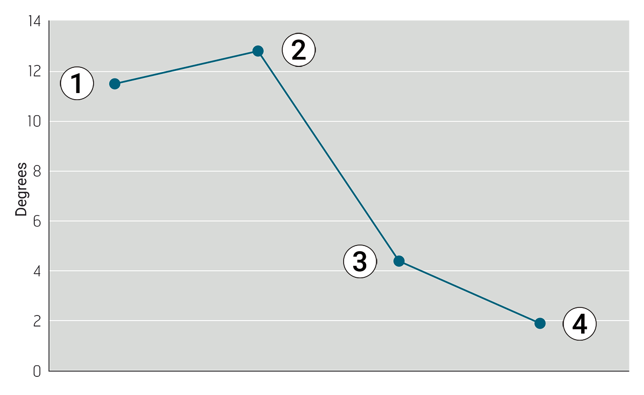
By introducing profiles with closed cross-sections for the cross-members, the stiffness in torsion is significantly improved, as in the graph and illustrations below.
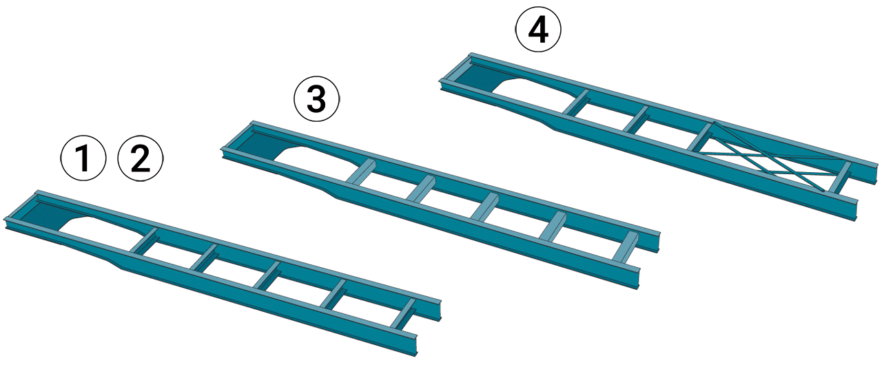
Comparison of the torsional resistance of an original design trailer chassis with open section cross-members (1), to the same chassis with reduced web thickness (2), a design with closed cross-member profiles (3) and a design with double cross-ties (4).
However, for optimum material utilization, the position of the cross-members is equally important. The redistribution or introduction of one or two additional cross-members influences the overall torsional stiffness. In general, the cross-members should be focused towards the rear part of the chassis. However, this shift has been exaggerated in practice many times. By moving cross-members forward or introducing an additional cross-member in a strategic region of the front part, the overall behavior can be significantly improved. Since a small rotation in the front part results in big displacements of the rear, increasing the torsional stiffness of the front could improve the overall performance.
Introducing cross-ties is another effective measure. To ensure optimum material utilization, it is important to design the cross-tie to only carry tensile loading in one bar and allow the other bar to buckle. Therefore, the bars should be slender and not welded to each other at the center. To demonstrate the effect of these measures, a comparison was made of the twisting angle resulting from a torsional moment applied at the rear of a common tipper chassis. The results from the calculations represent a unique case, but clearly illustrate the impact of these measures on the chassis stiffness in torsion. In all calculated cases, the total mass of the cross-members remained constant. That is, for the case where closed cross-sections were used, the thickness of the profiles was reduced. The results show that a reduction in web thickness results in a minor decrease in torsional stiffness compared to the original design, while introducing closed cross-members or a double cross-tie significantly improves the stiffness.
Fatigue
All trailers are subjected to fatigue loads during driving and loading. The life of a trailer chassis is determined by the load history, which consists of collected loads of varying number and magnitude. The appearance of the load history will vary depending on the type of trailer, road conditions and loading situation. When upgrading a trailer chassis using HSS, the sheet thickness of the structural parts is usually reduced. This reduction in thickness will result in an increased working stress level in the complete chassis. However, a stronger material will result in higher fatigue strength for the base material. For welded joints, however, this influence is limited due to the stress concentration and the initial imperfections introduced at the welds. Therefore, the fatigue life of welded joints is more dependent on design and manufacturing rather than choice of material. If the same weld joint design and weld quality are deployed, this will result in reduced fatigue resistance for the chassis.
Fatigue resistance
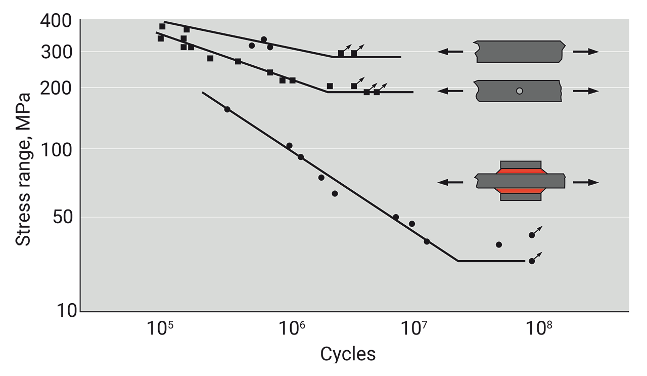
The fatigue resistance of a material is demonstrated in S/N curves, which are created by testing specimens using a load history of constant amplitude. This means that a specimen is subjected to the same load cycle repeatedly until it fails. After testing several specimens at different load levels, an S/N curve can be plotted. In the graph below, the upper curves show that the fatigue resistance is determined by the static properties of the material. In the lower right part of the graph, the fatigue resistance is determined by discontinuities in the specimen. Discontinuities can include surface texture from rolling of the sheet, cut edges, holes, notches and welds. These are listed in order of decreased fatigue resistance.
S/N Curves for specimens of rolled sheet, with punched hole and welded joint.
Why is the welded joint a critical area?
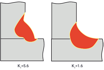
Welded joints have a much lower fatigue resistance compared to the base material due to the sharp geometry of the weld and residual stresses introduced from the heat input during welding. While the fatigue resistance of welds is often discussed in relation to microstructures, heat affected zones and hardness, the major cause of the weakening of the weld is local stress concentration and defects. All post-treatment methods of welds aim to reduce residual stresses and improve the weld geometry. To achieve good fatigue resistance, it is important to have a smooth transition radius and angle at the weld toe, as shown in the illustration below.
Sharp and smooth weld toe geometry.
Transverse versus longitudinal fatigue loading of a weld
Discontinuities in a weld are oriented in the welding direction and follow the root and weld toes. If the discontinuities are parallel to the principal stress direction, they have a small impact on the fatigue resistance of the weld. On the other hand, if the stresses are transverse to the weld direction, the fatigue resistance of the weld will be very low. For example, the fatigue life of an attachment bracket welded to the lower flange has less than 5% of the fatigue life of the weld between the web and the flange.
Start and stop positions
The start and stop positions of a weld are the most critical to its fatigue resistance. Since the welding process is not in a steady state, defects and inclusions are more likely to occur in these positions. Therefore, due to their limited length, tack welds have lower fatigue resistance than continuous welds. Tack welding of longitudinal beams should be minimized, and tack welds should be positioned in low-stress areas. The weld between the upper flange and the web is less sensitive to fatigue, since this area is mainly subjected to compressive stresses. It is important to design welded joints in general to allow the start and stop of the weld to be placed in low-stress areas. In some cases, fish-tail design can be used to move the start and stop positions away from the most highly stressed area, such as at the end of a reinforcement plate (see illustration below).
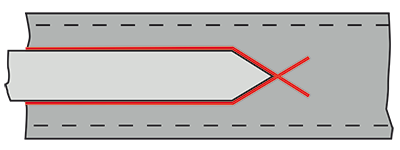
Fish-tail design can be introduced to move the start and stop-positions of a weld away from a high stress area.
Load history
The load history of trailers is irregular and random by nature, and the total number of load cycles during its life is in the region of 108–109 cycles. Even if the majority of load cycles have a very small magnitude, they can still be potentially critical for fatigue when combined with larger loads, which can be perceived as crack initiators. On the other hand, small loads can be viewed as crack propagators. Due to these combined effects, the fatigue limit found in constant amplitude loading vanishes in trailer applications. The only exception is when all loads in the complete history are lower than the fatigue limit. Therefore, it is important that welds in high-stress areas have good fatigue resistance, such as welds loaded in the lengthwise direction. Welds with less fatigue resistance should be placed in low-stress areas, such as near the neutral layer of the web of the main beams.
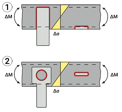
As an example, we can make a comparison of an alternative design for an attachment bracket welded to a beam that is subjected to bending in the vertical direction. When loaded in global bending, the maximum stresses occur at the flanges of the beam and vary in compression and tension over the neutral layer. The design at the top (1) in the illustration below has the attachment bracket welded near the flanges, with the start and stop positions of the weld located in the most highly stressed area of the beam cross-section. The configuration at the bottom (2) has the attachment bracket redesigned to be plug welded closer to the neutral layer. This results in the stress level at the welded joint being reduced by 50%, which increases the fatigue life 8 times compared to the previous design.
Reinforcement plates
When upgrading from conventional steel to HSS in order to develop a lightweight solution, there are some common pitfalls that can be avoided by implementing simple measures. The first and most important design advice is to keep the structure simple. Reduce the number of parts and utilize modern manufacturing techniques to integrate attachments and minimize the number of welded joints. For the chassis main beams, we recommend that you use a single piece for the flanges and the web throughout the full length of the trailer. This solution reduces the number of welds, especially in the transverse direction, which is important from a fatigue point of view.
Reinforcement plates are frequently used on both webs and flanges to increase the load-carrying capacity and stiffness of the chassis. While this measure can be beneficial from a static perspective, it can do more harm than good from a fatigue perspective.
In a main beam, manufactured from single pieces along the length without any reinforcement plates, the longitudinal weld of the I-beam will determine the fatigue life. When the trailer is loaded, the lower flange will be subjected to tensile stresses in the lengthwise direction in line with the weld. If a reinforcement plate is welded to the lower flange, there will be a transverse loading of the welded joint that reduces fatigue life by at least 8 times (see illustration below).
Introducing a reinforcement plate to the web or the flange also creates a stress concentration at the welded joint, since there will be a stiffness gradient in this area. Therefore, this weld joint will limit the fatigue life of the chassis and may cause cracking problems in an upgraded design where the working stress level is higher.
Landing gear attachment
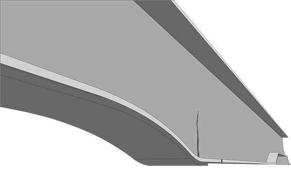
One of the most critical areas on a trailer chassis is the goose neck region. The height transition results in high stresses, which do not generally affect the trailer’s static load-carrying capacity. However, extra care is needed when designing secondary structures, such as the landing gear attachment, in this area.
If the landing gear attachment is designed to be welded to the flanges, the weld joint will be in the most highly stressed area of the beam cross-section. Redesigning the attachment bracket to be attached to the web instead moves the weld joint into an area with lower stresses (see illustration below). This will improve the fatigue life of the weld joint substantially (Example A).
To improve fatigue life of the landing gear the attachment should be placed close to the neutral layer of the main beam. A bolted connection will improve the fatigue life substantially (2).
Example A
It is common to design the landing gear in a conventional trailer chassis to be welded to a reinforcement plate that is attached to the lower flange in the neck region of the trailer, as in the illustration below. This weld is placed in a critical region from a fatigue perspective. When developing a lightweight trailer chassis and reducing the thicknesses, the working stress level will be higher. This will result in a reduced fatigue life for this weld if no redesign is performed. This example demonstrates how a redesign of the attachment bracket affects the fatigue life.
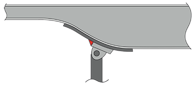
Landing gear attachment welded to the reinforced lower flange of a conventional trailer main beam.
The calculations are performed on a conventional main beam manufactured from mild steel (a) and an upgraded alternative in HSS (b) according to the illustration. The fatigue life of this weld in the conventional trailer chassis is assumed to be 16 years. The upgraded design assumes that the attachment bracket is welded directly onto the lower flange, without a reinforcement plate.
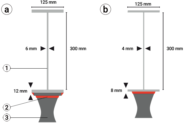
Geometry and cross-sectional properties of the conventional (a) and upgraded main beams (b) included in the calculations.
1) Main beam. 2) Reinforcement plate. 3) Landing gear attachment.
Moment of inertia: Ia = 87E-06 m4, Ib = 52E-06 m4.
Section modulus: Wa = 685E-06 m3, Wb = 348E-06 m3.
The nominal stress due to bending of a beam is given by:
This shows that the stress level at the critical weld is 100 MPa in the conventional chassis. It will be 100 × 2 = 200 MPa in the upgraded trailer. The fatigue life of a weld is related to the applied stress range by a power of 3; hence the fatigue life of the critical weld in the upgraded trailer will be reduced by:
That is, the fatigue life of the critical weld in the upgraded de-sign will be reduced from 16 years to 16 / 8 = 2 years!
If the welded joint is redesigned according to the illustration in the previous section about load history, and the critical weld joint is removed, the longitudinal weld between the flange and the web becomes the dimensioning factor from a fatigue perspective. The strength of a longitudinal weld is much higher than the transverse weld. If we compare the fatigue strength of these welds, we find that the critical weld at the attachment has a characteristic fatigue strength, FAT, of 63MPa but the longitudinal has a FAT of 125 MPa, as in the illustration below. This means that the longitudinal weld can tolerate twice the stress compared to the transverse weld.
So even though the working stresses have been increased by a factor of 2 in the upgraded I-beam, the fatigue strength of the critical weld joint has been improved by a factor of 2 through a simple redesign. Hence, we have maintained the fatigue life of the original design.
First rear axle attachment
As for the goose neck area, the hanger bracket region is a critical area on a trailer. Apart from vertical bending, lateral loads will be introduced in this area. It is therefore important to avoid welding at the edge of the flanges, since these are high-stress areas.
To reduce the stiffness gradient between the hanger bracket and the lower flange, it is beneficial to weld the bracket to an attachment plate. The plate must have sufficient thickness, and the welds between the plate and the flange must be positioned at least 20 mm from the edge of the flange. Variable flange width can be introduced to increase the bending moment capacity and the area available for attaching the hanger brackets. To further improve the fatigue life, the hanger bracket attachment can be designed as a bolted joint, as in the illustration below.
Any web stiffeners used to manage the local vertical shear loads in this region should be positioned in line with the loading direction from the hanger brackets. Placing the stiffener at a distance from the hanger bracket will introduce an additional bending of the lower flange and reduce the fatigue life significantly.
Placing the web stiffener at a distance from the hanger bracket introduces additional bending to the lower flange, which will rapidly reduce fatigue life. To improve the fatigue properties, any web stiffener in this region should be positioned directly in line with the hanger bracket. Introducing a wider flange increases the resistance to side bending and enables the welds to be placed at a distance from the critical area at the lower flange (2). To improve the fatigue life even further, a bolted joint could be introduced (2).
Cross-member attachment
For trailer chassis that are subjected to torsional loading, such as tipper or dump trailers and timber trucks, we strongly recommend using profiles with a closed cross-section for the cross-members. In most cases, this solution enables the cross-members to be welded straight into the web without any additional reinforcements. For heavy-duty vehicles, a web stiffener can be integrated in the cross-member attachment to increase stiffness and reduce stress levels in this area, as in the illustration below.
Profiles with open cross-sections can be used in trailers whose cross-members are mainly sub-jected to bending, e.g. curtain-siders, container carriers and vans. Openings for every profile can be cut into the web, and the profiles can be welded to the web plate of the longitudinal beam. However, it should be noted, that profiles with open cross-sections are not recommended for chassis subjected to twisting loads.
Yet another solution is to use an attachment bracket to distribute the stresses over a larger area. The attachment bracket can be welded, riveted or bolted to the web of the longitudinal beam.
Rear Underrun Protection Devices
Rear Underrun Protection Devices (RUPDs) significantly enhance the safety of car occupants during collisions with heavy vehicles. The most recent RUPD standard mandates a substantially stronger structure than its predecessors, making high-strength steel tubes the ideal choice for this purpose.
By incorporating Strenx® 700 and Strenx® 960 steels in the main cross beams and support legs, the structure achieves the required strength while maintaining a reasonable weight limit. The SSAB tubes portfolio offers a variety of high-strength steel tube dimensions in rectangular, square, or circular shapes. All are specifically engineered to meet the RUPD standard requirements.
It is important to note that RUPD performance depends on the overall behavior of the structure, not only the crossbeam. Consequently, the connection between the crossbeam and support legs, the support legs themselves, and the connection between the support legs and the chassis should be considered carefully during the design stage.
While the RUPD structure might possess adequate strength to endure the specified loads, the primary beam of the chassis could experience failure. To address this issue, reinforcing the chassis main beam through the incorporation of local stiffeners or employing higher grades of steel in the chassis can provide effective solutions.
Adding extra stiffener to strengthen the structure where the crossbeam connects to the support legs can effectively prevent or delay local buckling of the crossbeam and improve the load-carrying capacity of the RUPD (1). On the downside, this solution might allow stones or dirt to gather. Adjusting the stiffener by tilting it downward can fix the problem (2).
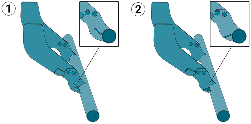
Rear underrun protection devices with support stiffeners leaning up (1) and down (2).
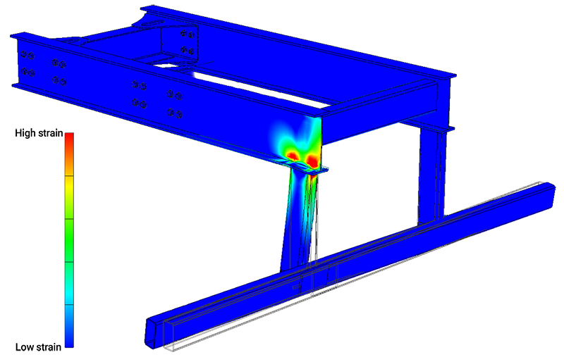
Equivalent strains.
The information in this report is only applicable to SSAB’s products and should not be applied to any other products than original SSAB products.
This report provides general results and recommendations for SSAB steel products. This report is subject to SSAB’s Terms of Use. It shall be the user's responsibility to verify that the information contained herein is correct and is suitable to be used for the particular purpose and application of the user. The report is intended to be used by professional users only who possess adequate expertise, qualification and knowledge for the safe and correct use of the results and recommendations in this report. This report is provided “as is”. The use of the report is at user’s own discretion and risk and that users will be solely responsible for any use of this report. SSAB disclaims any liability for the content or potential errors of this report, including but not limited to warranties and condition of merchantability or fitness for a particular purpose or suitability for individual applications. SSAB shall not be liable for any kind of direct or indirect damages and/or costs related to or arising therefrom, whether special, incidental, consequential or directly or indirectly related to the use of, or the inability to use, the report or the content, information or results included therein.

